Industrial Gearbox Rebuild: Planetary Gear Systems, Reducers, and Speed Increasers
What Teardown Reveals, What Repair Involves, and How to Keep It from Happening Again
When a gearbox goes down, the repair decision starts with understanding what type of gearbox it is, why it failed, and what it actually takes to fix it correctly. Those three questions aren’t as straightforward as they look — and getting any one of them wrong determines whether the rebuilt unit comes back in six months with the same failure or runs for years.
Houston Dynamic has rebuilt industrial gearboxes of all types for over 50 years. This guide covers the fundamentals: how planetary gear systems work, what separates the three main gearbox types — including the gear box designs we service most often — where gearboxes fail most often and why, and what a proper rebuild actually involves for each.
How a Planetary Gear System Works
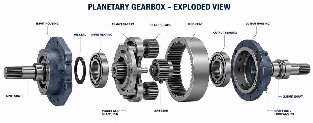
A planetary gear system is built around three components: a central sun gear, a set of planet gears that orbit around it, and a ring gear that surrounds the entire assembly. A planet carrier holds the planet gears in position and transfers their combined output to the output shaft.
The defining characteristic of the planetary design is shared load distribution. In a parallel shaft gearbox, one gear mesh handles all the torque. In a planetary system, multiple planet gears share the transmitted load simultaneously — three planet gears each carry roughly one-third of the total torque. This is why planetary systems achieve significantly higher torque density for their size than any parallel shaft design at the same horsepower rating.
Planetary gear systems are used wherever high torque output is needed in a compact envelope: conveyor drives, mixer drives, winches, press drives, extruders, and high-ratio speed reduction applications. They are also the basis for epicyclic gearboxes, which use the same sun-planet-ring architecture in different fixed and rotating configurations to achieve different ratio and torque characteristics.
The same design that makes planetary systems torque-dense also makes them maintenance-sensitive. Planet bearings rotate on their own axes while simultaneously orbiting the sun gear. Getting oil to them consistently, across that moving geometry and at all operating conditions, is harder than lubricating a fixed parallel shaft bearing. Lubrication system problems show up in planetary gearboxes faster than in most other designs.
What Is the Difference Between a Planetary Gearbox, a Gear Reducer, and a Speed Increaser?
All three are industrial gearboxes. What separates them is the relationship between input and output speed and torque, and the gear geometry used to achieve it. A parallel shaft speed reducer gearbox and a planetary gear reducer both cut speed and multiply torque — they just get there through different gear arrangements.
| Gearbox Type | Input vs. Output Speed | Input vs. Output Torque | Common Gear Arrangement | Typical Applications |
|---|---|---|---|---|
| Planetary gear reducer | Input faster than output | Input lower than output | Sun / planet / ring gear | Conveyor drives, mixer drives, winches, high-ratio reduction |
| Parallel shaft reducer | Input faster than output | Input lower than output | Offset helical, worm, or bevel gear stages | General industrial drives, HVAC equipment, pumps, fans |
| Speed increaser | Input slower than output | Input higher than output | Helical or double-helical gear sets | Centrifuges, high-speed compressors, turbine-driven generators |
The planetary gearbox is a subset of gear reducer — it reduces speed and multiplies torque using the sun-planet-ring configuration. Parallel shaft reducers achieve the same result through a different arrangement: offset input and output shafts connected through helical, worm, or bevel gear stages.
Speed increasers run the power flow in the opposite direction. The low-speed shaft is the input; the high-speed shaft is the output. Most of the mechanical components are identical to a reducer of the same ratio — the demands on the repair are different because of the higher output speed, not because the gears are fundamentally different.
What Causes Industrial Gearbox Failure
Most gearbox failures trace to one of four root causes. The damage found on teardown — scored gear teeth, spalled bearings, worn seals — is the result of one of these conditions, not the cause itself. Treating the result without identifying the cause is why rebuilt gearboxes fail again.
Lubrication Failures
Lubrication failure is the most common root cause across all gearbox types. It shows up in several forms:
- Wrong viscosity: oil that is too thin for the operating temperature doesn’t maintain adequate film thickness at the gear mesh or bearing contact surfaces. Metal-to-metal contact follows. Oil that is too thick doesn’t flow adequately to high-speed components and generates heat from internal friction.
- Contamination: water, process fluid, or particulates in the lubricant degrade film strength and act as abrasives at the gear mesh. A contaminated sample doesn’t look wrong until you analyze it. By the time the contamination is visible, significant damage has usually already occurred.
- Inadequate flow: clogged filters, worn oil pump, blocked passages, or an undersized system that can’t keep up with heat generation under high-load conditions. Planetary gearboxes are particularly susceptible because the lubricant has to reach planet bearings that are moving both on their own axis and around the sun gear.
- Thermal breakdown: lubricant that has exceeded its operating temperature range loses viscosity and chemical stability. This can happen progressively over a long service period or acutely during an overload event.
For guidance on catching these issues before they cause failure, see our proactive maintenance planning guide.
Gear Tooth Damage
Gear tooth damage in industrial gearboxes falls into four categories, each pointing to a different cause:
- Pitting: surface fatigue at the gear tooth contact zone, appearing as small craters on the tooth face. Micropitting indicates lubricant film thickness is inadequate for the contact stress. Macropitting indicates the contact stress is approaching or exceeding the material’s fatigue limit.
- Scoring: adhesive wear caused by film breakdown under high contact stress. Scoring leaves directional scratch marks along the tooth flank and can develop rapidly. If a gearbox is run through a scoring event, even briefly, the damage to the tooth surface changes the contact geometry in ways that accelerate further degradation.
- Wear: progressive removal of tooth material at the contact zone, changing the tooth profile over time. Moderate wear on a gear that isn’t causing other problems may be acceptable. Wear that has changed the tooth profile enough to increase dynamic loads needs to be addressed.
- Bending fatigue: crack initiation at the tooth root that progresses to fracture. A broken gear tooth is an immediate shutdown condition. The fracture surface tells you whether the crack initiated from a material defect, a stress concentration at the root geometry, or high dynamic loading.
Bearing Failures
Bearings are the most frequent failure component, but the failure mode tells you what actually went wrong. Fatigue spalling that develops gradually over the expected service life is a normal end-of-life failure. Fatigue spalling that appears early indicates overloading, inadequate preload, or wrong bearing fit. Contamination-induced wear produces a different surface texture than fatigue. Lubrication starvation leaves characteristic heat marks and smearing.
Reading bearing failure mode correctly determines whether the repair is a straightforward replacement or whether there is an underlying system problem that will destroy the replacement bearing at the same rate.
Overloading and Installation Problems
A gearbox operating beyond its rated capacity will fail faster than its design life regardless of maintenance quality. This happens because application requirements changed after the original selection, because the gearbox was undersized at specification, or because process conditions produce shock loads the rating doesn’t account for.
Installation problems — misalignment at the couplings, inadequate foundation, improper interference fits on shaft connections — introduce additional loads that don’t appear in the nameplate rating. Misalignment that would be tolerable in a low-speed reducer produces significant dynamic loading in a high-speed increaser.
What Planetary Gearbox Repair Actually Involves
A planetary gearbox teardown surfaces failure information that isn’t available any other way. The sequence and what to look for at each step:
- Full disassembly and documentation: planet carrier, planet gears, bearings, sun gear shaft, ring gear, and housing come apart completely. Component orientation, timing marks, and assembly sequence are documented before anything moves.
- Planet carrier inspection: the carrier bores that hold the planet gear pins are measured for wear, roundness, and concentricity. Out-of-tolerance carrier bores produce uneven load distribution across the planet gears even after everything else is correct. This is a common miss on inadequate rebuilds.
- Planet bearing fits: planet gear bearings run on pins pressed into the carrier. The interference fit between pin and carrier bore, and the clearance fit between bearing and gear bore, both affect bearing life. Wrong fits — even by a small margin — significantly reduce bearing service life at operating speed.
- Gear tooth contact pattern: before cleaning the gears, the contact pattern on each gear mesh is documented. The contact pattern shows where load was actually being carried on the tooth face, whether the gears were running in alignment, and whether any asymmetric loading was present. This information guides reassembly and can identify housing or shaft deflection problems that caused the original failure.
- Ring gear inspection: the ring gear internal tooth surface is inspected across the full face width. Ring gears in planetary gearboxes carry load at multiple mesh points simultaneously. Wear that is concentrated on one side of the face indicates a misalignment problem in the housing or carrier.
- Multi-stage considerations: multi-stage planetary reducers require every stage to be disassembled and inspected, not just the stage where visible damage occurred. Failures that originate in the input stage transmit through the downstream stages and produce secondary damage that looks like separate failures. Inspecting only the obvious damage stage and reassembling produces a rebuild that fails again within one operating cycle.
- Reassembly and timing: planet gears in some designs must be timed to specific positions relative to each other and the sun gear to distribute load evenly. This is documented by the OEM and must be followed precisely. Timing errors produce uneven load distribution and premature failure even when all components are in specification.
Gear Reducer and Speed Increaser Repair: Where the Process Differs
The rebuild sequence for parallel shaft reducers and speed increasers follows the same teardown-inspection-root cause-repair-test framework. What changes is what to look for and where the repair tolerances are tightest.
Parallel Shaft and Helical Gear Reducers
- Helical reducers generate axial thrust at every gear mesh because of the helix angle. Bearings on helical gear shafts are loaded both radially and axially. Bearing failures in helical reducers often present as axial vibration before radial vibration becomes significant — an inspection point that gets missed when vibration analysis focuses only on radial readings.
- Worm gear reducers use sliding contact at the mesh rather than the rolling contact of helical gears. The bronze worm gear wears against the hardened steel worm. Wear rate in worm reducers is more sensitive to lubricant viscosity and temperature than in helical designs — the oil film is what separates the sliding surfaces. A worm reducer that has seen temperature excursions or contamination has typically consumed a disproportionate amount of its bronze gear life.
- Contact pattern verification after reassembly is critical for all parallel shaft reducers. The contact pattern shows whether gears are meshing correctly across the full tooth face. Incorrect patterns indicate housing bore misalignment, shaft deflection, or assembly error. A gearbox reassembled with an incorrect contact pattern will develop tooth damage at the rate the contact stress dictates — regardless of what the nameplate rating says.
- Tapered roller bearing preload in reducer rebuilds must be set to specification. Too much preload generates heat and reduces bearing life. Too little preload allows the shaft to move axially under load, producing impact loading at the gear mesh. Preload is set by measured endplay or bearing crush, not by feel.
Speed Increaser Gearboxes
Speed increaser repair is more demanding than equivalent reducer work because the output speed amplifies every imperfection.
- Balance tolerances are tighter for increaser components than for reducers running the same ratio. A residual imbalance that produces acceptable vibration on a reducer output shaft running at 600 RPM produces vibration forces that are orders of magnitude higher on an increaser output shaft running at 6,000 RPM.
- Journal bearing clearances require precise measurement and control. High-speed increasers typically use hydrodynamic journal bearings rather than rolling element bearings because rolling element fatigue life becomes limiting at very high speeds. Journal bearing performance depends on maintaining the correct oil film thickness across the full operating speed range. Clearances outside of specification — even slightly — produce either inadequate film at low speed or instability at high speed.
- Test stand verification at operating speed is not optional for speed increaser rebuilds. Performance at low speed during startup does not predict performance at full operating speed. Temperature, vibration, and oil pressure must all be verified at the actual operating condition before the unit returns to service.
When to Rebuild vs. Replace a Gearbox
Rebuild is the right answer in most situations. The cases where replacement makes more sense:
- The unit is a standard catalog gearbox that is readily available and rebuild cost approaches replacement cost
- Internal inspection reveals housing damage that cannot be repaired economically — cracked housings, damaged bearing bores that cannot be sleeved back to tolerance
- The application requirements have changed and the existing gearbox is no longer the right selection for the duty
- A replacement unit with a shorter lead time is available and schedule is the primary constraint
For custom, large, or long-lead-time gearboxes, rebuild almost always wins on both cost and schedule. A custom planetary reducer with a 20-week manufacturing lead time can often be rebuilt in weeks, even with significant internal damage, once the failure is understood and parts are sourced.
Emergency gearbox service is available when the equipment can’t wait for a standard turnaround.
Houston Dynamic
Houston Dynamic has rebuilt industrial gearboxes of all types for over 50 years: planetary gear systems, parallel shaft reducers, speed increasers, and specialty designs across a full range of sizes and manufacturers. Our Houston facility handles complete teardown, failure analysis, precision machining, component replacement, balancing, and test stand verification in-house.
If you have a gearbox that needs evaluation, contact us with the nameplate information and a description of what failed. We will tell you what the rebuild involves and what the timeline looks like.
Contact Us for a Gearbox Rebuild Quote →
Frequently Asked Questions
A gearbox rebuild is a complete disassembly, inspection, root cause analysis, and reassembly process that returns a gearbox to its original operating specifications. Every component is removed, measured, and evaluated. The failure mode and its cause are identified before any repair work begins. Worn or damaged components are repaired or replaced. The unit is reassembled with documented clearances and fits, then verified on a test stand before returning to service. A bearing swap or partial repair is not a rebuild.
Most industrial gearbox failures trace to one of four root causes: lubrication failure (wrong viscosity, contamination, inadequate flow, or thermal breakdown), bearing failure (often downstream of a lubrication problem), gear tooth damage (pitting, scoring, wear, or bending fatigue), or overloading and installation problems (misalignment, improper fits, or operation beyond rated capacity). The damage found on teardown is the result of one of these conditions — identifying and correcting the root cause is what prevents the same failure from recurring after rebuild.
A planetary gearbox uses a central sun gear, a set of planet gears that orbit around it, and an outer ring gear that surrounds the assembly. A planet carrier connects the planet gears and transfers their output. Multiple planet gears share the transmitted load simultaneously, which allows planetary systems to achieve higher torque density in a compact package than parallel shaft designs of comparable size. The planet carrier output rotates more slowly than the sun gear input, producing speed reduction and torque multiplication.
Both reduce speed and multiply torque, but they use different gear arrangements. A planetary gear reducer uses the sun-planet-ring configuration, with load shared across multiple planet gears simultaneously. A parallel shaft reducer uses offset input and output shafts connected through helical, worm, or bevel gear stages, with load carried through a single gear mesh at each stage. Planetary reducers are more compact for a given torque rating; parallel shaft reducers are simpler in construction and more common in general industrial applications.
The output speed of a speed increaser amplifies every imperfection in the rebuilt assembly. A small residual imbalance acceptable in a reducer produces substantial vibration forces at increaser output speeds. Journal bearing clearances that are within tolerance range for a reducer may produce film instability in an increaser at high speed. Misalignment that a reducer handles without issue creates significant dynamic loading in an increaser running at 5,000 RPM or higher. Speed increaser rebuilds require tighter balance tolerances, more precise bearing clearance control, and test stand verification at actual operating speed.
Rebuild time depends on gearbox size and complexity, the extent of internal damage, and component availability. A straightforward rebuild on a mid-size parallel shaft reducer can be completed in days to a couple of weeks. Large planetary gear systems with significant internal damage and long-lead-time replacement components take longer. Houston Dynamic provides timeline estimates after teardown inspection, when the full scope of damage is known and parts can be sourced.
The most useful information is the manufacturer name and model number, gear ratio, input and output shaft speeds and horsepower, a description of the failure symptoms, and any vibration or oil analysis data already collected. If the unit is already disassembled, photos of the internal damage are helpful. For emergency situations, getting the unit to our Houston facility for teardown and inspection is the fastest path to an accurate scope and timeline.
Share this post:
Recent posts: